34+ transfer function to block diagram
Transfer Functions and Block Diagrams 2. Also it can be used together with transfer functions to represent.

Canonical Form For Closed Loop Systems Control System System Control
26 points Find the final transfer function for the following block diagram.

. Then we can write for the last part of the block diagram. A block diagram can be used simply to represent the composition and interconnection of a system. Transfer function block diagram.
Block Diagram Simplification Example 1 Rearrange the following into a unity -feedback system Move the feedback block 𝐻𝐻𝑠𝑠 forward past the summing junction Add an inverse block on 𝑅𝑅𝑠𝑠to. Ask Question Asked 7 years 5 months ago. Viewed 2k times.
The tricky thing to calculate the transfer function for these block diagrams is actually the algebra you have to be careful with some sign or with some number that we do not place or forget out. Y G s x Now we can move on further through the diagram by. Modified 7 years 5 months ago.
Hence b c This system has the same transfer function determined in part a because multiplication of. Enter the email address you signed up with and well email you a reset link. Block diagram models The block diagram is a diagrammatic means to represent the cause-and-effect relationship of system variables.
It consists of unidirectional operational blocks that. Transfer Function Block Diagram. Show and draw the resulting block diagrams one step at a time for.
Transfer function models 3. Electrical Engineering questions and answers. The most common technique used for modeling linear time-invariant systems is the block diagram with the mathematical model represented as a transfer function.
Also the transfer function of a single block is its output-to-input transform. Lets call the edge that goes into the G s block x. 113 4 4 bronze badges.
Transfer functions and their corresponding block diagrams are shown as a reference for how to manipulate or construct one from the other. Denis Davydov Denis Davydov. A transfer function G s.
Intro to block diagrams ME 431 Lecture 5 1. Reduce the following block diagram to a single transfer function. Review differential equation solution process 4.
The first step in creating a transfer function is to convert each term of a differential equation with a Laplace transform as shown in the table of Laplace transforms.

Feynman Diagrams For The Electron Positron Interaction In The Download Scientific Diagram

Block Diagram For Open Loop Control System Control System System Control
2
2

Ultra High Resolution Linear Ion Trap Orbitrap Mass Spectrometer Orbitrap Elite Facilitates Top Down Lc Ms Ms And Versatile Peptide Fragmentation Modes Molecular Cellular Proteomics
Pin By Pngst6 On Robust Optimal Adaptive Control Lie Algebra

Limitations Of Pll Simulation Hidden Oscillations In Matlab And Spice Deepai

Control System And Types Of Control System Electrical Paathshala System Control System Transfer Function
2
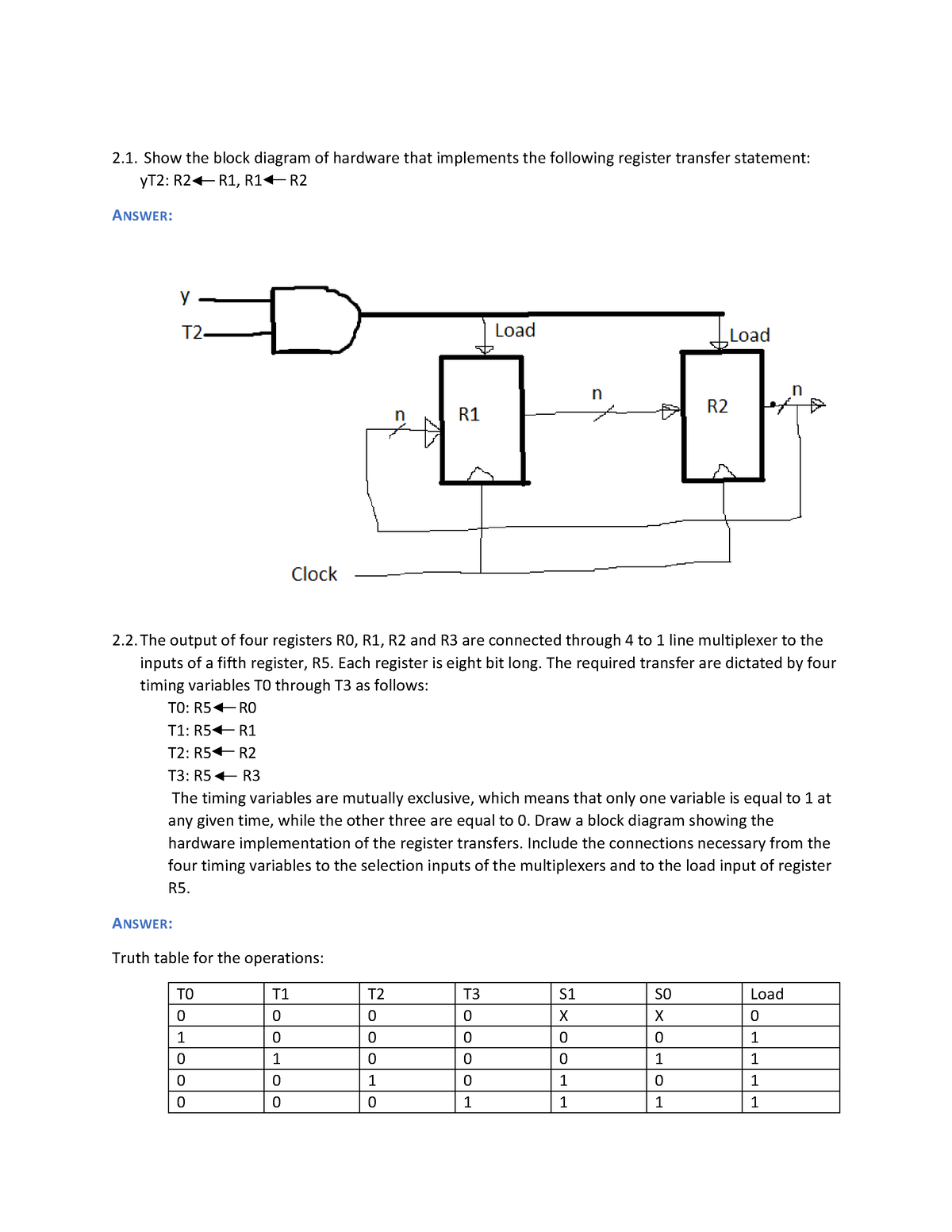
4 6015049101878495567 Copy Show The Block Diagram Of Hardware That Implements The Following Studocu

Resource Html Uri Celex 01985r3821 20160222 Eng Xhtml L 2002207en 01015801 Tif Jpg

Dynamic Behavior Of Closed Loop Control Systems Control System Laplace Transform Transfer Function
Family Tree In Excel Creating A Family Tree Template In Excel
2

Reduce The Block Diagram To A Single Transfer Func Transfer Function Block Diagram Diagram
Drawing In Excel Examples How To Use The Drawing Toolbar
2